Adapted from James Brewster's AEGC 2018 paper by Bell Geo's guest blogger Simon Emsley

James Brewster, Bell Geospace - Senior Software Engineer

Simon Emsley, Independent Geophysicist - Guest Article Blogger
Introduction
You are an exploration manager and your team is searching for economically viable resources and there are a number of options available to you for exploration. Traditionally, these are surface based geophysical methods, that may be land based or marine based. Airborne platforms are routinely used in mineral exploration more so than for other reserves. There are clear advantages of airborne platforms in terms of speed of coverage of large survey areas, particularly in reconnaissance phases but these methods are finding applications in shallow hazard mitigation and shallow velocity modelling.
Gravity methods are one of the many techniques that can be deployed in or on an airborne platform. Gravity gradiometry is the preferred method of acquiring data to map density variations in the subsurface. The question is, if you are going to commission a gravity survey and assuming that a gravity gradiometer survey is selected, which instrument design should you select?
An internet search produces results that may be a specific named brand, but is this the best design that will give you the results that you need. Fortunately, there is an analytical framework that can help answer this question

Which Gravity Gradiometer Design Should Be Selected?
There are two gravity gradiometer designs currently available for commercial survey operations and other instruments are in the late stages of pre-deployment research. These gradiometer systems differ from one another with respect to the number and orientation of sensing accelerometer pairs.
We can look at the three gradiometer designs from a numerical point of view. Two gravity gradiometer designs are manufactured by Lockheed-Martin:
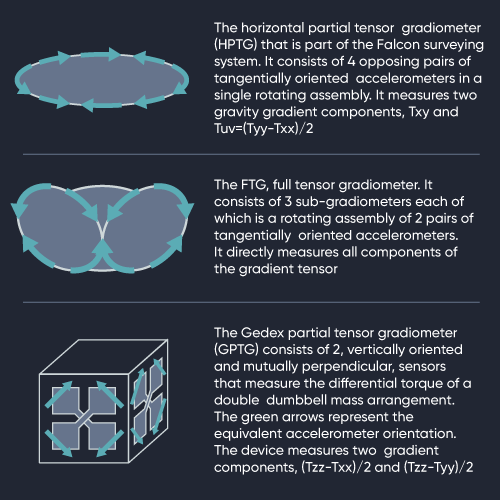
1. the full tensor gradiometer (FTG)
2. the horizontal partial tensor gradiometer (HPTG)
3. the two component gradiometer (GPTG)
What's the Difference?
The main difference is the number and orientation of the gradient sensing components. The data recorded, the signal resulting from changes in subsurface geology, are not uniformly distributed between the differently oriented sensors. This means that some sensor orientations will detect stronger signals than others. This can be modelled using sources that have simple geometries.
The instrument sensitivity is defined as the total signal detected by the gradiometer. This is summed over all available channels and provides a means of comparing the predicted signal to noise level.
Comparison of Capabilities
A comparison of the capabilities of the different instruments requires a framework for assessing the effect of these differences on both signal strength and noise level. This approach is based on three aspects:
-
Sensitivity: The ability to detect a given source
-
Noise: The level of noise that remains after an optimal noise reduction process
-
Inversion: The ability to solve for the source geology
The quantitative interpretation of gravity gradiometry requires some form of inversion and the presence of noise will cause errors in the resulting model of the subsurface.
Sensitivity
The analysis looks at the sensitivity of the gradiometer as a function of dimensions, of the data set, centered over a spherically symmetrical source. This shows that the FTG and GPTG show similar sensitivities at small distances from the center of the source. At larger distances, the FTG design has the largest sensitivity, with the GPTG and the HPTG lower by factors of the square root of two and 3.08 respectively.
Noise
The results of the noise analysis varies dependent on the components measured. The largest noise reduction is seen in components of the FTG. Some components show the same reduction in noise level for all three instruments.
Inversion
As may be imagined the error level is high if the distances are small and the HPTG requires greater distances to reach the limiting error value, with the exception of the horizontal position error. At small distances, the FTG and GPTG show similar values before flattening out to different constant values. At larger distances, the relative inversion errors in the GPTG and HPTG are higher than those of the FTG and are again, factors of the square root of two and 3.08 respectively.
Conclusion
The analyses available shows that gradiometer designs that directly measure Tzz, the FTG and GPTG, perform relatively better than the HPTG when directly over the source. The HPTG can be thought of as a side-looking device. The importance of this aspect is somewhat lessened in airborne surveying because even if a flight line passes directly over a source, significant portions of that line will still be located such that the source is at a more favorable angle to be detected. Any quantitative conclusion from this analysis is relative to the raw noise level of the instrument. It can tell us nothing about how the gradiometer will perform under particular conditions such as high vertical acceleration. What it does give, is a means of evaluating the noise will have on the final product.
The analyses presented indicates that for the HPTG instrument to match the performance of an FTG instrument the noise level needs to be less than that of the FTG by a factor of 3.08. The equivalent value for the GPTG, being developed, is 1.41.
This quantifies the advantage the FTG has over the other two designs due to the number and orientation of its sensors.
So now we know, to get the best results select a system that uses an FTG instrument rather than a “side looking device”.
You are welcome to leave comments on this post below or find the full paper for download from the Bell Geospace resource library.